True Airspeed Meter
Developed By: Eric Richman and Jim Roal ME 406 Experimental Design March 17, 1997Introduction
A true airspeed measurement system is a combination of sensors, data acquisition equipment, a calculation and data storage medium, controlling software and an output device. The system is capable of providing true airspeed measurements for use in automobile, aircraft, wind tunnel, and other gas flow systems.
This project was proposed as a means of furthering the development of an initial true airspeed measurement system. This initial system included the primary components (excluding static pressure) but lacked an easily usable software base. This system was also relatively costly in terms of the components used.
This project involves identifying inexpensive, readily available components, combining the sensors, data acquisition and output equipment, developing easy to use application software, and unit testing. The result of the project is a small, inexpensive true airspeed measurement device with 1 to 2% full scale accuracy. This system provides accurate airspeed by incorporating volume airflow with the effect of air density (temperature and barometric pressure) that is known to effect actual airspeed
This report describes the development of this system and provides the needed details and specifications for building and operating an identical system.
Background
True airspeed relates the actual speed of air molecules past a specific point. This specific measure is not readily available with current equipment because action at a molecular level is not easily discernible. Typically, airflow is measured and loosely related to airspeed.
Airflow is commonly measured using two methods. The first is a "hotwire" that relates the cooling properties of flowing air over a heated wire. The loss of heat from the wire and current air temperature is used to calculate the mass flow rate of air. A second method is the impact pressure differential from a Pitot tube or force of air on a rotating cup. These methods also relate the force to a mass airflow. What each of these methods lack is an adjustment for the density of the air which effects the force of the air. This effect causes an error when converting mass airflow to airspeed.
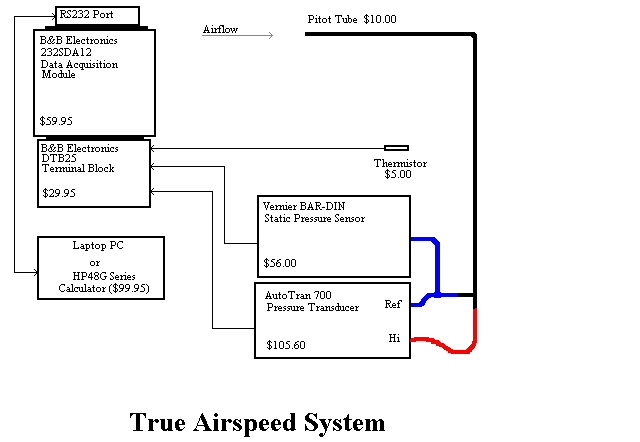
True airspeed calculation (see formula in appendix) includes differential pressure, static pressure, and temperature. The airspeed system developed for this project uses a Pitot tube for pressure differential, a barometer module for static pressure, and a thermistor for temperature.
Additional requirements for accurate true airspeed measurement include a data acquisition system that can concurrently read the signals from each of the three inputs so that calculations of airspeed can be made with instantaneous data. Also needed is an output devise capable of collecting data in real time through the data acquisition module, performing the necessary time-stamping , and calculating and displaying the recorded values and true airspeed.
Finally, the placement of the three sensors must be made to ensure accurate data collection. The thermistor must be placed such that it is able to read air stream temperature and not be influenced by solar input or nearby heated or cooled surfaces. The Pitot tube must be placed such that it is aimed into and parallel to a reasonable steady stream of air. The static pressure sensor must be far enough away from any turbulence or modified air stream that might effect static air conditions.
The initial airspeed measurement system incorporated pressure differential and temperature but did not include static pressure input. The new system developed in this project includes all three inputs as well as other software features that make the system easier to use and provides more useful data.
System Components
The initial system primary components were:
- Pitot Tube with pressure transducer for pressure differential
- Thermocouple for temperature
- Digital transmitters (2) for data acquisition
- HP48GX calculator for storage, calculation, and display
- Pitot Tube with pressure transducer for pressure differential
- 5k nominal thermistor and circuit
- Static pressure sensor
- Data acquisition module
- Optional use of either an HP48G series calculator or any DOS based PC system for storage, calculation and display
Data Acquisition
The previous system used two Omega data transmitters that daisy chain together to communicate with an RS232 port. These modules are costly and utilized a complicated data stream. To reduce cost and speed up data transfer to the HP48G series calculators we used a B&B 232SDA12 data acquisition module. This module has 12 bit resolution on 11 analog input channels, 3 digital input channels, and 3 digital output channels. The module also has an internal 5VDC, 5ma reference voltage output. This module will connect to any RS232 device for data communications. The module can be powered by the serial port of a PC but not by the HP48G calculator. Fortunately, the module can be powered by a 2.5mm power plug which was used to supply 12VDC power to the module.
Temperature
The thermocouple used in the initial system provides the needed data but relies on a very small output range. This limited range makes accurate temperature assessment more difficult. A thermistor provides sufficient temperature ranges for expected conditions of about -20?C to 80?C. The thermistor has a large resistance change per degree temperature change compared to the much smaller potential difference change of a thermocouple. A 5k ohm nominal thermistor was chosen for this system and was already available. These items are very low cost and available in a variety of configurations.
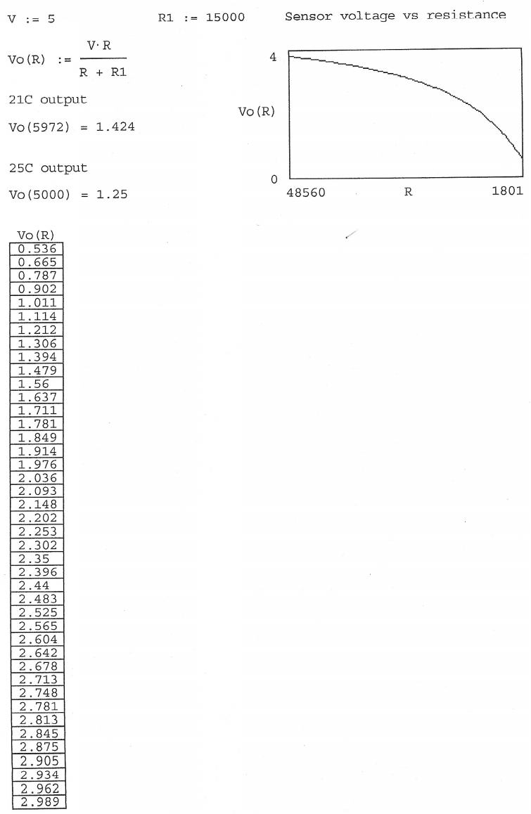
The thermistor circuit was made by connecting a 5kohm nominal thermistor in series with a 15kohm resistor between the 5V reference output and the analog ground pin on the module. A wire was then connected from an analog input channel to the junction between the resistor and thermistor making a voltage divider. This voltage is related to the resistance of the thermistor, which in turn is related to the temperature. A curve fit equation was programmed into the software we developed to convert the measured voltage (resistance) of the thermistor into the temperature.
Differential Pressure
The initial system used a Pitot tube and Autotran model 700-02"1204 series delta pressure transducer with a range of 0" to 2" of water. This sensor requires a 12VDC input and outputs a voltage between 1VDC and 5VDC which can be converted to pressure difference between its two ports through a linear transfer function. This system works well for this application and no changes were made as part of this project. Other pressure transducer products may be available that are lower cost, smaller in size, or have more convenient pressure ranges.
Static Pressure
The static pressure sensor we used is a Vernier BAR-DIN sensor which outputs a 0 to 5VDC at a pressure range from .8 to 1.15 atmospheres. This sensor has a 5 pin DIN connector which happens to be the same as a computer keyboard. We obtained a keyboard extension cable and cut it so we could wire the static pressure sensor to our system. The BAR-DIN sensor requires a 10ma, 5VDC input which is more current than the SDA232 module can produce on its 5VDC reference circuit. To eliminate this problem we installed a 5VDC regulator so the sensor input voltage was supplied separately.
System Software
The previous software was for the HP48G series calculator only. This software only logged the temperature and delta pressure and it did not calculate or display anything. One of the primary goals of this project was to have a realtime display of the true airspeed while logging data. We wrote software for both the HP48G series calculator and PC systems because they each have their advantages. The HP48G software allows a person without a laptop computer to build this system inexpensively since the HP48G calculator is under $100 to purchase. Many people who would be interested in using this airspeed meter system already have access to a laptop so software was written in C++ for this.
HP48G software development
The software written for the HP48G was done using several subroutines (see HP48G version manual). These subroutines each perform a part of the total function. This was done so that different applications could use these common functions. There are two main functions most users will use: EXEC and DLOG. The function EXEC will clear the display and show true airspeed in the center, with the correct units, while it logs data in the background. The function DLOG jest logs the data with no display. The reason DLOG was written is because the HP48G is rather slow at performing the required calculations and it must be run at a port speed of 1200 baud to eliminate errors. Eliminating the calculation and display of airspeed allows more data to be stored. The data stored is: Time in HP48G format, delta pressure in Pascals, Static pressure in Pascals, and temperature in Kelvin. This data is stores in a 4 column matrix called A. Matrix A starts with a row of zeros and each new data point is a new row inserted into the top of the matrix. True airspeed is not stored in the A matrix however the user can extract any row from the A matrix and use the function SPEED to calculate it. The A matrix can be uploaded to a PC and used in most spreadsheet software. The data in the A matrix will be just over a second apart when using the EXEC function and under a second apart using the DLOG function. See Appendix for software manual and source code.
PC version software development
The software for the PC is written in Borland C++ version 3.0 using many of the routines and the header file supplied by B&B. Since even an X computer has a clockspeed about 500 times faster that the HP48G calculator we were able to make the C++ version do more than the HP48G version. The program called ASPEED.EXE will acquire the data, calculate and display all input voltages and hexidecimal values as well as calculate and display true airspeed, static pressure, delta pressure, seconds since program start, and time in seconds between data points (see C++ version manual). The user can start, pause and resume data logging at any time while the program is running. The time between data points in the log file can also be changed at any time even while logging data. The log filename can be specified on the command line at program start or the default ASPEED.TXT filename will be used. The log file will contain the following data: Time in seconds since program start, true airspeed, delta pressure, static pressure, temperature, and air density. There is a configuration text file called ASPEED.CFG which can be changed to accommodate different delta pressure sensors for different airspeed applications. See Appendix for software manual and source code.
System Cost
One of the advantages of the new system is the relatively low cost. The table below provides details on the cost of the primary components necessary for this system as used on a DOS based PC. The total estimated cost of approximately $223 is markedly less than the estimated $575 cost for the previous system.
New system hardware cost| Part Description | Company | Price |
|---|---|---|
| 12bit, RS232 data module 232SDA12+ | B&B Electronics | $59.95 |
| 25 pin terminal block, DTB25 | B&B Electronics | $29.95 |
| Static pressure sensor BAR_DIN | Vernier Software | $56.00 |
| 5kohm nominal thermistor | - | (Est) $5.00 |
| 5VDC regulator, 276-1770 | Radio Shack | $1.49 |
| 15k ohm resistor, 271-1337 | Radio Shack | $.49 |
| Delta pressure sensor | AutoTran 700 | $105.60 |
| 12V power supply | - | (Est) $15.00 |
| Pitot Tube | - | (Est) $10.00 |
| Total | $283.48 |
For a complete operating system where a PC is not available, the HP48G calculator and a few additional components can be combined to provide true airspeed measurement. These additional costs are detailed below.
Additional Hardware Cost For HP Calculator System| Part Description | Company | Price |
|---|---|---|
| HP48G calculator | Hewlett Packard | $99.95 |
| Serial cable #2609 | EduCalc | $22.95 |
| Null modem adapter 26-264 | Radio Shack | $3.99 |
| Gender changer 26-243 | Radio Shack | $4.99 |
| Total | $131.88 |
References and Sources
Roberson J.A., Crow, C.T., Houghton Mifflin 1993, Engineering Fluid Mechanics, Fifth edition
Omega Engineering P.O. Box 4407 Stamford, CT 06907-0047
B&B Electronics Manufacturing Company 707 Dayton Road P.O. Box 1040 Ottawa, IL 61350
Phone: (815) 433-5100 Web: http://www.bb-elec.com e-mail sales@bb-elec.com
Vernier Software 8565 SW Beaverton-Hillsdale Hwy Portland, OR 97225-2429
Phone: (503) 297-5317 web: http://www.vernier.com e-mail: info@vernier.com
EduCalc (800)535-9650 http://www.educalc.com/products/hp48g.htm
Radio Shack Fort Worth, TX 76102
Phone: 1-800-THE-SHACK
System Testing and Results
Bench testing and field testing of the unit was necessary to determine relative accuracy of the output and ensure that the unit was not adversely effected by field conditions.
Bench testing was performed using the bench airflow blower in the WSU-TC fluids lab and the Alnor airflow meter, model 8575, 2% of full scale reading accuracy. The table in the appendix shows the comparative results of these tests. The airspeed system reading was shifted by 3.3% of full scale compared to the Alnor at approximately 13 meters per second. This is a comparison with an airflow meter (not airspeed) and can serve as only an indication of reading accuracy.
We also compared the static pressure from the system with the fluids lab barometer. The system read within 1 mm Hg (133 PA) of 106,391 Pa full scale reading capability. This is within 0.1% of full scale. Temperature output was also compared and read within 1 degree of the fluids lab thermometer. This is 1% of full scale capability.
A final test compared the pressure differential output of the system with the Dwyer tester. At 100% of flow we got 106.7 Pa compared to the Dwyer reading of 107 Pa for a full scale (497 Pa) accuracy of 0.06%. At 40% of flow we got 77.7 Pa compared to the Dwyer reading of 78.6 Pa for a full scale (497 Pa) accuracy of 0.18%.
A series of field trials were also performed to ensure that the unit would perform without fault due to electrical system interference, vibration or handling. In all tests of the completed system, no anomalies were found.
Conclusions and Recommendations
Based on the testing performed, we believe the unit performs as designed and provides an inexpensive method of measuring true airspeed in the field with a minimum of equipment. The unit performs well compared to existing more expensive flow meter equipment. The unit is also fairly rugged for field use. however, the following should be considered when performing test runs.
- The thermistor should be placed away from the vehicle or other heat generating equipment and well within the measured airstream.
- The static pressure measurement (low pressure side of Pitot tube in this system) should be at least one vehicle height above the vehicle roof based on previous testing.
- The data acquisition, pressure transducer, and barometric pressure sensors should be housed within the vehicle to avoid damage from the elements.
Options to modify the system include alternate or multiple delta pressure sensors, addition of relative humidity.
Multiple pressure transducers could be installed to provide a larger range of airspeed measurement. The addition of relative humidity sensor could be easily accomplished and provide another small increase in measurement accuracy and versatility.
APPENDIX
- C++ version software manual
- HP48G series version software manual
- C++ version source code
- HP48G series source code
- Airspeed Formula
- Thermistor curve fit
- Bench testing spreadsheet
- System schematic
C++ version software manual
True Airspeed Meter
Software written by: Jim Roal for: WSU Tri-Cities, Richland, WA.
This software is written is Borland Turbo C++ V3.0. The basic software for interfacing with the B&B 232SDA12 was written by B&B. I used this code as a starting point for the true airspeed software.
File list:
| aspeed.c | C++ source code. |
| sda.h | Header file for interfacing the 232SDA12. |
| s232sda.lib | Library file for the 232SDA12 software. |
| aspeed.exe | True airspeed Windows software. |
| aspeed.cfg | Configuration file for the delta P sensor. |
| adata.txt | Output file of the data logged with aspeed.exe. This file may not exist until aspeed.exe is run. |
| aspeed.plt | This is a basic plot file for GNU plot for windows. This will display the speed vs time plot. You must remove the first row in adata.txt before running this. |
| aspeedd.plt | Same as above except it is the DOS version. |
Basic use
You must have the delta P sensor configuration file created and the proper data entered before running aspeed.exe. Using a text file editor (dos edit or windows notepad) create the file called aspeed.cfg (if it does not already exist). Enter the following data all on the first line seporated by a single space:
[shift voltage] [maximum reading in pascals]
For instance, the Autotran 700 starts at 1V with no pressure difference. It is a 0 - 2 inches of water sensor. Converting that to pascals it is a 0 - 497.68 pascal sensor. aspeed.cfg should have the following line in it:
1.0 497.68
Now you are ready to use the system. The main program (aspeed.exe) requires at least 1 command line parameter: the port number. This must be the com port number from 1 to 4. The complete list of command line parameters are as follows:
aspeed [port#] [log file] [save resolution]
where "log file" is a file name you can select in place of the default adata.txt and "save resolution" is the number of seconds between data points in the log file. You can specify a save resolution as low as 0 but the system will only save data as fast as the PC and port speed will allow. You can also specify a save resolution in fractions of a second. For instance you could specify a save resolution of .25 which would save 4 data points per second (.25 seconds between data points).
Once you start the program you will see digital inputs and outputs displayed in the upper left. While these do not effect the airspeed program they are displayed in the event someone may want to use them. The outputs can be cycled on and off by pressing the key corrosponding the the channel to change.
All analog channels are also displayed in both voltage and hexidecimal even though the airspeed system only uses the first three and channel 13. The output of the airspeed system takes up the lower right section of the screen. The following keys are active during program execution:
| F1 | This resets the delta pressure sensor zero value by averaging the next 25 samples and shifting all new data by the negative of that value. Obviously you must do this when the pressure at the delta pressure sensor ports are equal. |
| F2 | This will start/stop data logging. You can pause the logging and resume at any time as long as you do not exit and restart the program. If you want to erase the data and start over you must exit the program and restart it. |
| F3 | This will stop displaying the digital channels and show the current delta pressure sensor configuration parameters. This does not change the state of the digital outputs. Pressing F3 again resumes normal operation. |
| F5 | This resets the min/max speed readings. |
| F7 or END | This exits the program. |
The following keys allow the user to scale the save resolution at any time during execution:
| + | This will add .25 seconds to the current value. |
| - | This will subtract .25 seconds to the current value. |
| * | This will increase the current value 50%. |
| / | This will decrease the current value 50%. |
The time between data points displayed on the screen will show as "ET" in seconds. Next to this value is time in the seconds since the program was started shown as "total".
HP48G series version software manual
True Airspeed Program March, 1997 for the HP48G series calculator Writtem by: Jim Roal For: ME406 at WSU Tri-Cities
This set of programs will allow the user to read and log true airspeed data using an HP48G series calculator, a SDA23212+ data acquisition module from B&B electronics, a barometer (static pressure) sensor from Vernier software, a simple 5k ohm nominal thermister, a delta pressure sensor (AutoTran model 700D2), and other attaching hardware and wiring. For the system to operate properly you must set the IO parameters so that the baud rate of the data port on the HP48G is 1200. Use the IOPAR variable listed below. You also need a null modem adapter to connect between your HP48G serial cable and the B&B module. The B&B module must be powered through the 2.5mm power jack with a 12VDC source. You can use vehicle 12VDC power (eg. cigar lighter) to power the unit.
The software currently is set up fot a 0 - 2" of water delta P sensor which is good to about 28m/s.
Below is a list of files and thier purpose.
EXEC 284 03-08-97 12:31p
This is the main program that you will use. This program will use GO to get the data from the B&B 2432sda12+ module. Then it will use AIRS to convert that data into pressures and temperature and store this info with a time stamp (received from GO) in a vector. This vector is then inserted into the top row of the A matrix. Next SPEED will be used to calculate and display the airspeed in m/s. The latest air density value is also stored in a variable called RHO. After running EXEC or DLOG this value can be seen by pressing the RHO button in the VAR menu.
DLOG 156 03-08-97 12:32p
Same as EXEC except that no airspeed is calculated or displayed. The data is simply stored in the A matrix. You can extract a row from this matrix and use SPEED to calculate the airspeed. This function is intended to me used for logging data to be downloaded into a PC and manipulated there.
SPEED 148 03-08-97 12:24p
Calculates airspeed from the 1x4 vector created in AIRS. You can use this program to calculate speed from any row in the A matrix.
AIRS 595 03-08-97 12:29p
This is the program that will parse the incomming data and calculate the delta pressure in pascals, the static pressure in pascals, and the temperature in kelvin. Then it will store this data in the A matrix.
GO 68 03-08-97 12:24p
This program will send the command string to the sda23212+ and wait for 6 characters to be received.
ZERO 24 03-08-97 12:24p
This is a constant you can set to compensate for offset in the delta pressure sensor. It is in pascals. You should start out with 0 as the value to see if any affset is needed. You can use GO and then PRS3 to see the voltage value or you can view the A matrix after a sample run. The value in the A matrix is in pascals.
IOPAR 41 03-08-97 12:24p
This is the HP reserved variable for setting the IO parameters correctly to use these programs. Copy this into your HOME directory.
SETA 55 03-08-97 12:24p
This resets the A matrix to a single row of zeros to start with a fresh log file.
A 36 03-08-97 12:24p
This is the log matrix. It must have a single row of zeros to start with. AIRS will insert new rows on top as they are created. The data is as follows.
| column 1: | Time stamp in HP format: hh.mmss See the HP48G owners manual for more info on this format. |
| Column 2: | The delta pressure in pascals. |
| Column 3: | The static pressure in pascals. |
| Column 4: | The temperature in kelvins. |
There is a row of zeros at the bottom of the A matrix which is the starting row. This row is required to start the program. Do not delete the A matrix ever. Use SETA to clear the matrix for new data. Notice that airspeed is not in the A matrix. This is done since I assume this data will be transfered to a PC and manipulated there. Any spreadsheet can parse this data and perform the simple calculation to find airspeed and air density.
Airspeed = sqrt(2*(deltaP pa)/rho)
rho = (static pressure pa)/(287 * temp K)
PRS3 276 03-08-97 12:24p
This will parse the data from the GO function into the voltages received. You really dont need this except for diagnosis.
Below is the source code for AIRS. You can change this for use with different delta P sensors. See the comments to the right of the code below. The software is configured for the Autotran 700 now. This sensor outputs a voltage from 1V to 5V. Thats why the 1 - command on line 5 is there. It shifts this reading to 0V to 4V.
%%HP: T(3)A(D)F(.);  @ True airspeed program written by Jim Roal @
\<< DUP 1 1 SUB NUM
256 * SWAP DUP 2 2   @ This routine will parse the incomming string @
SUB NUM ROT + 4.99   @ and calculate the DP, static pressure & temp @
4096 / * 1 -         @ the 1 - command is a volt shift for the 700DP. @
124.42 * ZERO -      @ 124.42 is pa/v for a 0-2"h2o sensor @
SWAP DUP 3 3 SUB     @ you can change this to the pa/v of a different @
NUM 256 * SWAP DUP   @ meter. @
4 4 SUB NUM ROT + 5
* 4096 / .077 *
.809 + 101325 *
SWAP DUP 5 5 SUB
NUM 256 * SWAP DUP
6 6 SUB NUM ROT +
4.99 4096 / * DUP
15000 * SWAP 4.99
SWAP - / ABS LN
6.394 + 5071 SWAP /
41.95 - SWAP DROP 4
ROW\-> DUP A SWAP 1  @ This data is inserted into matrix A @
ROW+ 'A' STO
\>>
HP48G Series source code
EXEC
%%HP: T(3)A(D)F(.);  @ Data logging program written by Jim Roal @
\<< CLLCD            @ This program will execute the proper routines @
  WHILE KEY 0 ==     @ to log and display airspeed. It stops when any @
  REPEAT GO AIRS     @ key is pressed @
SPEED 5 DISP
  END DROP
\>>
DLOG
%%HP: T(3)A(D)F(.); @ data logger written by Jim Roal @
\<< 1
  WHILE KEY 0 ==    @ same as exec except no display @
  REPEAT DROP GO
AIRS
  END
\>>
AIRS
%%HP: T(3)A(D)F(.);  @ True airspeed program written by Jim Roal @
\<< DUP 1 1 SUB NUM
256 * SWAP DUP 2 2   @ This routine will parse the incomming string @
SUB NUM ROT + 4.99   @ and calculate the DP, static pressure & temp @
4096 / * 1 -         @ the 1 - command is a volt shift for the 700DP. @
124.42 * ZERO -      @ 124.42 is pa/v for a 0-2"h2o sensor @
SWAP DUP 3 3 SUB     @ you can change this to the pa/v of a different @
NUM 256 * SWAP DUP   @ meter. @
4 4 SUB NUM ROT + 5
* 4096 / .077 *
.809 + 101325 *
SWAP DUP 5 5 SUB
NUM 256 * SWAP DUP
6 6 SUB NUM ROT +
4.99 4096 / * DUP
15000 * SWAP 4.99
SWAP - / ABS LN
6.394 + 5071 SWAP /
41.95 - SWAP DROP 4
ROW\-> DUP A SWAP 1  @ This data is inserted into matrix A @
ROW+ 'A' STO
\>>
GO
%%HP: T(3)A(D)F(.);
\<< "!0RA:)" XMIT DROP
TIME 6 SRECV DROP
\>>
SPEED
%%HP: T(3)A(D)F(.);
\<< DUP OBJ\-> DROP 287
* ABS / DUP '1_kg/m
^3' * 5 RND 'RHO'
STO / 2 * ABS \v/ 5
RND '1_m/s' * SWAP
DROP SWAP DROP
\>>
SETA
%%HP: T(3)A(D)F(.);
\<<
[[ 0 0 0 0 ]]
'A' STO
\>>
Calculations
Air density:
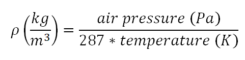
Where Pstatic is read from the static pressure sensor and Tair is read from the thermistor. This equation is based on ideal gas characteristics of the air.
Airspeed:
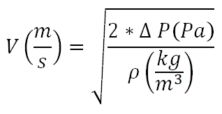
Where _P is read from the delta pressure sensor.
Temperature:
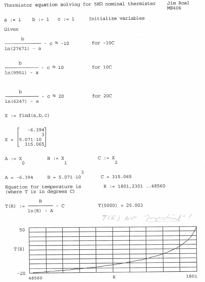
 Where Vout is the voltage between the thermistor and the resistor.
Click here for the original report (pdf)
Update 2017
Here are the files I have remaining from this project in a ZIP file: aspeed.zip. I am missing the actual executable, and all the HP48 files but all the source is there. If someone wanted to do this today it would likely involved all different parts, and a mobile device app versus a calculator app. Prices for most of the components are likely lower, and the components are better too.
Several years after this project was created, someone patented this concept and even referenced this project. You can see that here. At the time this project was hosted in WSU servers but it has since been removed.
Here is a newspaper article explainign an award from WSU for our work on this true airspeed meter.