INSTALLATION INSTRUCTIONS
1999-2002 Crown Victoria / Grand Marquis
ĀSupercharger Kit
Congratulations on choosing what we feel is the best supercharger kit on the market. Proper installation is the key to long and trouble free operation. Please read and understand thoroughly all of the instructions presented here. We have made major improvements on the Rev II Kit, especially on issues associated with installation time.Ā Every possible effort has been made to assure a quality and complete product.Ā Please check the completeness and condition of your kit as received. A checklist is included with your warranty information, which lists all the parts and quantities.Ā If there are any missing or damaged parts, please call us.Ā We will make every effort to remedy the situation in a timely manner.
1.Ā 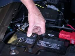 ĀĀĀ2.
ĀĀĀ2. 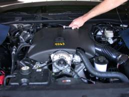
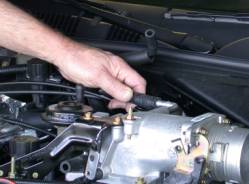
1. Disconnect negative ground cable from battery.
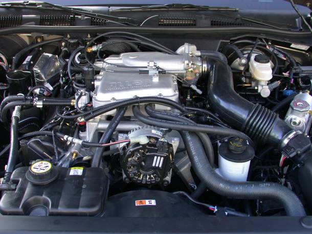
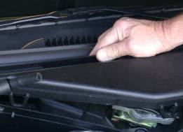
2. Remove plastic engine cover.
3. Remove EEC processor from driver side footwell. And set aside.
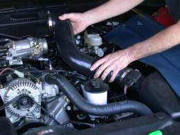
4. Remove mass air sensor to throttle body tube.
4.  5.
5. 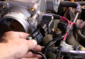
5. Disconnect vehicle wiring harness connectors from ignition coils; throttle position sensor, idle air, EGR solenoid valve, EGR Pressure Transducer, Temperature Sensors, fuel pressure,Ā and fuel injector connections.
Ā6. 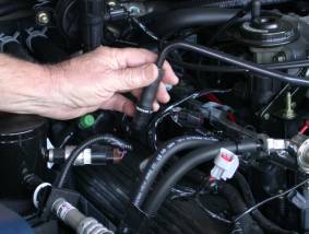 ĀĀ7.
ĀĀ7. 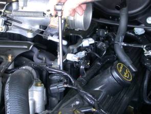
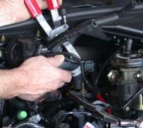
6. Remove PCV hose from vehicle.
7. Remove ignition coils.
8.  ĀĀ11.
ĀĀ11. 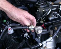
8. Remove throttle and cruise control cables.
9. Remove idle air valve, and hose from vehicle.
10. Remove crankcase vent hose from vehicle.
11. Relieve fuel system pressure and disconnect spring lock couplings. A special tool is required for this.
12.  ĀĀ14.
ĀĀ14. 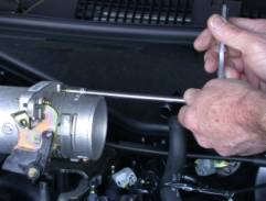
12. Remove PCV, and vacuum hoses from vehicle.
13. Drain engine coolant from petcock valve on bottom of radiator. Remove radiator cap to speed this up process, and more completely drain engine.
14. Remove throttle body from intake manifold.
15.  Ā 16.
Ā 16. 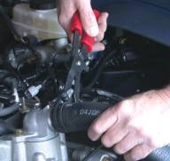
15. Disconnect water heater hose from intake manifold.
16. Remove upper radiator hose from thermostat housing.
17.Ā 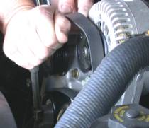 Ā18.
Ā18. 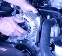
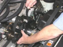
17. Remove accessory drive belt from vehicle, using a 3/8ö drive breaker bar to loosen the tensioner.
18. Loosen 2 alternator bolts, and disconnect alternator wires.Ā Remove Alternator and set aside.
19. Remove steel bracket which supports throttle cables and stuff.
20. Loosen EGR tube retaining nut at EGR Valve.
19.  ĀĀ20.
ĀĀ20. 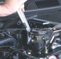
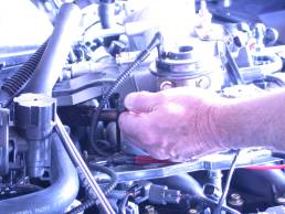
21. Remove Intake Manifold bolts, including the ones retaining the water outlet. There is a heavy steel bracket on the rear driver side of the manifold which needs to be removes before all the bolts can be removed. This bracket is bolted to the engine in 2 places. The bolt shown in 21.5 goes through the intake manifold.Ā The other bolt/stud goes into the back of the cylinder head. To remove this stud, procure the smallest handed person available and 13mm & 15mm wrenches. Remove the nut from the stud using the 13mm wrench, as well as the bolt which is the other fastener securing the sheet metal bracket.Ā After this bracket is removed, the stud can be removed using the 15mm wrench. Te heavy steel bracket should now be able to be removed.
22. Remove water outlet.
21. 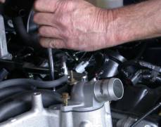 ĀĀ 21.5
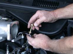
23. Remove thermostat housing, thermostat and O-Ring from the Intake manifold.
25.  Ā
Ā
24. Remove Intake Manifold.
25. The stud and nut can now be re-installed (without heavy steel bracket). Be sure to re-install bolt too.
26. Remove Intake Manifold Gaskets.
27. Vacuum any dirt or debris from the Intake Manifold flanges and cover with duct tape or equivalent.
28.  ĀĀ31.
ĀĀ31. 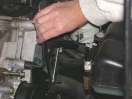
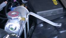
28. Remove 2 nuts and 1 bolt power steering reservoir mount on the front cover. Remove lower stud replace it with a new stud, without the integrated nut. (supplied in kit)
29. Remove the 4 bolts retaining the water pump pulley.Ā Remove pulley.
30. Remove front cover bolts, which will need to be replaced for the mounting of the Idler Pulley Mount.Ā To determine which bolts need to be removed, If not obvious to you, hold the mount up to the front cover and position the hole over the stud you just replaced.
31. Position Idler Pulley Mount and retain with bolts provided.Ā (Torque to 17-22 ft-lb.)
34.ĀĀ 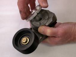 ĀĀĀ35.
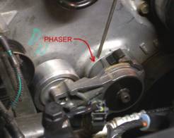
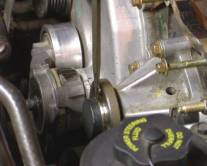
32. Remove belt tensioner from vehicle.
33. Remove pulley from tensioner.(do not discard!)
34. Install supplied pulley onto tensioner.
35. Install the supplied ōphaserö in between tensioner and front cover. (use supplied longer bolt and washer)
Ā36. 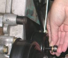 Ā
Ā
36. Install the pulley removed from the tensioner onto the Idler bracket. (use supplied bolt and washer)
37. Transfer the EGR Valve from the stock manifold to the new manifold with bolts and gasket provided. (Torque to 17-22 ft-lb.)Ā Be sure to replace the gasket to assure proper functioning.
38. Transfer the throttle body from the stock manifold to the new manifold using stock bolts.Ā Reuse the gasket as long as it is not damaged.
39. Transfer the Idle air control valve from the stock manifold to the new manifold using supplied bolts.Ā Reuse the gasket as long as it is not damaged.
40. Transfer the engine temperature sensor from the old manifold, to the new one. (Use Teflon sealant)
41. Transfer one fuel rail bolt from the old manifold to the new manifold (passenger side-rear).Ā Be sure to retain the phenolic spacer supplied to insulate the fuel rails from the manifold.
42. Transfer EGR solenoid to new manifold using the bolts supplied, and attach the hose from the manifold to the lower port.Ā Connect the upper port to the EGR valve with supplied hose.
43. Transfer fuel pressure test (Schraeder) valve from old fuel rail to new fuel rail (driver side). Use Teflon tape.
44. Re-install cap on the Schraeder valve.
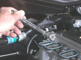
45.ĀĀ 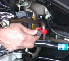 ĀĀ45.5
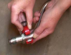
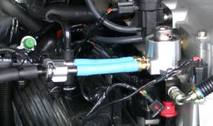
45. Since the EGR Valve has been re-located, the EGR Tube must be ōModifiedö. This can be done with common hand tools.Ā (shown Sears 51252 tubing cutter) The tube must be cut in two (2) places and mended with brass crush collars on the end of a flexible stainless steel tube.Ā
45.9 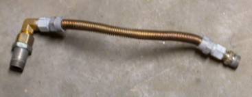 Ā 46.
Ā 46. 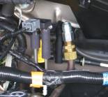
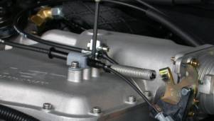
46. Tighten all EGR feed tube connections. The photos are shown without the woven heat shield for clarity. (Be sure to install heat shield before continuing)
47. You are tired now and should take a 10 minute break!
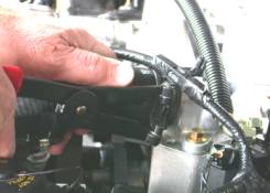
48. Relocate the EGR pressure transducer rearward by gently bending the steel tubes on the EGT tube. This is to clear the bypass valve in the new manifold.(see photo 46)
49.  50.
50. 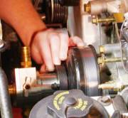
49. Remove black plastic protective sleeve on water pump shaft. This may require a hammer and sharp chisel or a sharp knife. Try not to mar the precision machined surface under the sleeve.
50. Position new water pump pulley onto the water pump and attach the intercooler water pump with the 4 supplied bolts. These can be tightened with a standard 8mm box end wrench. A pair of water pump pliers (spanning 2 of the bolts) can be used to keep the assembly still while tightening each bolt.
51.  Ā52.
Ā52. 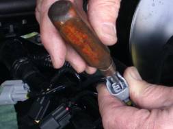
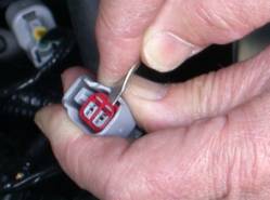
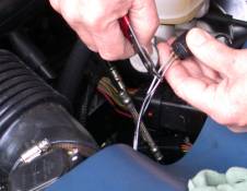
51. The injector plugs need to be swapped to match the 30# injectors. Disassemble the connectors as shown. Cut and strip wires.Ā Crimp terminals to wires and insert into new connector. Be sure not to reverse the polarity of the wires. (red wire to left as installed into injector) Swap all 8 injector plugs.
52.  52.5
52.5 
52. A small notch may need to be cut into the windshield wiper arm cover. Remove the cover and trim.Ā Re-install after the supercharger assembly is installed and verify clearance.Ā Re-trim and fit if necessary.
53. Re-install the intake manifold gaskets on to the cylinder heads.Ā Make sure they have not been damaged in any way.ĀĀ (Protective tape or equivalent must be removed now)
54. Set the Intake manifold / Supercharger assembly onto the engine.Ā Be sure not to damage the gaskets during this procedure.Ā The wiring harness will need to be lifted slightly at the rear of the engine to allow it back into the proper position.Ā This is best performed with a person on each side of the vehicle to gently guide it into place.
55. Install the intake manifold bolts supplied (9 hex flange bolts) and tighten in a crisscross pattern.Ā Repeat this procedure until all bolts are snug and then torque to 17-22 ft-lbs.
56.  Ā 57.
Ā 57. 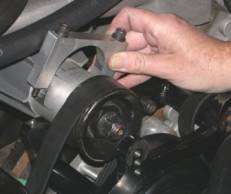
56. Install alternator bracket to front of engine, hand tighten the bolts. The belt must be routed properly before attempting this step. Refer to Figure 2.Ā (P13.) for belt routing.
57. Install drive housing clamps and bolts. Tighten bolts (8-11 ft-lbs). Torque alternator bolts to 17-21 ft-lbs.
58.  ĀĀ 63.
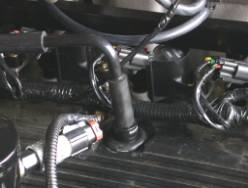
58. Connect feeder tube fitting to EGR Valve and tighten. There may be some slight alignment of the flexible stainless steel tube required before this is achievable.
59. Re-install ignition coils and retaining bolts, and tighten.
60. Plug in electrical connectors for the ignition coils, fuel injectors, throttle body, idle air control valve, etc.
61. Re-connect heater hose to intake manifold fitting.
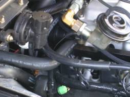
62. Attach the Evaporative canister hose to the passenger side 3/8ö vacuum tube. (See Figure 1) The existing hose may need to be shortened slightly for a proper fit.
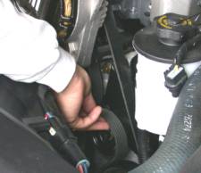
63. Using supplied hose and stock hard plastic tube, connect the hose from PCV valve to the driver side 3/8ö vacuum tube. The hard plastic hose will need to be trimmed as shown in photo)
64.  ĀĀ 65.
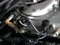
64. Re-attach the throttle and cruise control cables and return spring. Check for proper operation and adjust cruise cable attachment if necessary.
65. Connect vacuum hoses to EGR valve and solenoid. (See Figure 1)
66.  Ā67.
Ā67. 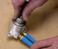
66. The wires for the inlet air temperature sensor need to be lengthened. Supplied in the kit are color-coded wires and crimp connectors as well as black corrugated split loom. We recommend soldering and shrink-tubing the connections if possible.Ā Connect the wire to the new temperature sensor located in the plenum above runner #1.
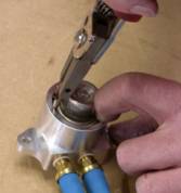
67. Remove the fuel pressure regulator from the stock fuel rails, and insert it into the adapter.Ā
68.  67.
67. 
68. Re-attach the circlip to retain the regulator.
69. Install the regulator assembly into the fuel rail. ConnectĀ vacuum hose to regulator. (shown not connected)
70.  71.
71. 
70. Install thermostat (or supplied 180░ thermostat; 9 psi kit only), O-Ring, and thermostat housing, using the stock bolt and the nut and washer supplied. The fuel fitting may need to be removed to insert the stock bolt. Re-install the upper radiator hose/clamp.
71. Re-connect the fuel line (if disconnected).
72. Replace the stock alternator pulley with the supplied pulley. This requires an impact wrench!Ā If you do not have an impact wrench, most auto parts stores will be able to swap pulleys for you.
73. Insert alternator bolts into bracket as shown on figure 2. (top on pass side, bottom on driver side)
74.  ĀĀ75.
ĀĀ75. 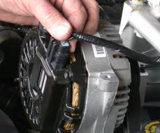
74. Install alternator onto new bracket and rout belt properly around all pulleys. The tensioner must be relieved to its slack position during this process. It may be easier to slip belt over idler pulley (shown) last as it has no flange. Belt will be very tight when first installed, but will stretch and loosen (and wear in) after driven.Ā After driven 10-20 miles it will need to be tightened by rotating the alternator position. (move bolt up to next hole as necessary)
75. Re-connect electrical connector and wire to alternator.
76. Install the rubber air inlet tube from the mass air flow sensor to throttle body and tighten clamps
77. Re-attach formed rubber hose from air inlet to idle air valve. (hose and connector supplied)
78. Connect valve cover breather hose from driver side valve cover to air inlet tube.
80. 
79. Mark hole locations in wheel-well cover using water tank, and drill holes. (1/4ö drill).
80. Attach Intercooler coolant tank to firewall cover with supplied hardware.
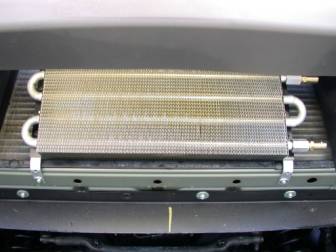
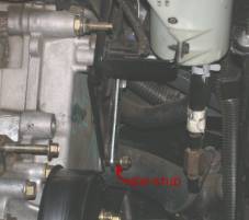
81. With the Heat Exchanger for the Intercooler bolted to its mounting brackets, position the assembly under the valence toward the passenger side of the opening and the fittings on the driver side.Ā Mark hole positions using a magic marker. Remove assembly and drill holes using #29 drill bit (supplied) for the self tapping screws (supplied).Ā Be careful if you drill to deep you will hit the AC condenser.
82. Connect all intercooler hoses as shown in figure 1.
83. Re-fill engine cooling system and re-install cap.Ā Close the petcock first!
84. Fill the Intercooler water tank with coolant (50/50 Water Glycol mixture). It may be necessary to burp the system by loosening the petcock on the top of the water pump.Ā Install the Radiator Cap.
85. If your kit is equipped with a high flow fuel pump, it can be installed now.Ā Follow instructions included with pump.
86. Install the chip into the EEC processor. Follow instructions included with chip. We recommend cleaning the connections very carefully using a tang broken from a plastic fork or finger nail, and then scotch brite. Re-Install EEC processor, and connector.
87. The battery cable can now be re-connected.
88. Check for any stray tools or spare parts which may hinder the starting of the vehicle.
89. Start engine and check for any fuel or coolant leaks, as well as adequate working clearance between parts.Ā Remove intercooler tank cap, and verify flow, top off if necessary. Replace cap.
90. After initial test drive of 10+ miles the accessory drive belt will loosen slightly.Ā The alternator must now be rotated into the next bolt hole on the driver side of the vehicle. Both bolts holding the alternator to the bracket will need to be loosened to perform this operation.Ā A small pry-bar or screwdriver may be necessary to rotate the alternator to position, as well as relieving the tensioner.
91. Re-tighten the bolts to 17-22 ft-lbs and YouÆre done!
Revision 1.02 1-02-03 SMG
ĀĀĀĀĀĀĀĀĀĀĀĀĀĀĀ
ĀĀĀĀĀĀĀĀĀĀĀ
Dear Customer:
Thank you for your recent purchase of
the Allen Engine Development Inc. supercharger kit for your 2000-2002
Crown Victoria / Grand Marquis.
Your Kit serial #________
Your Supercharger serial #_______
Calibration Code___________
Date purchased_______
Warranty period______
Please keep this in your records in the event of a warranty claim.
|
Revision |
Date |
Approved By |
Description |
|
1.01 |
12-13-02 |
SMG |
Updated header and address. Added revision block.Ā Added 180 thermostat. |
|
1.02 |
1-02-03 |
SMG |
Updated hose routing for new cast pump |
|
1.03 |
1-3-03 |
Jim |
Updated 81 condenser |
|
1.04 |
10-10-03 |
SMG |
New belt length 1223 |