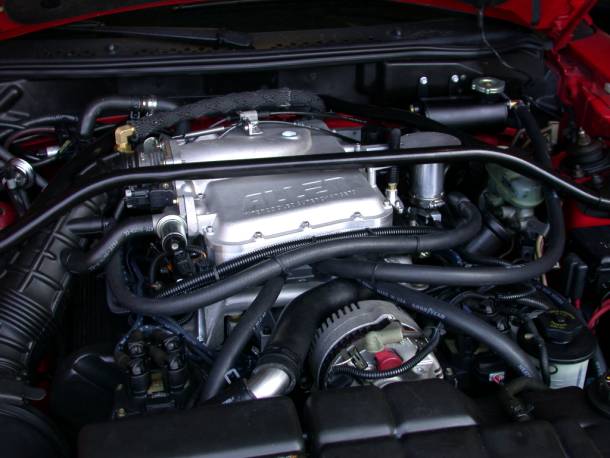
1996-1998 Rev. II Mustang GT Supercharger Kit
Congratulations on choosing what we feel is the best supercharger kit on the market. Proper installation is the key to long and trouble free operation. Please read and understand thoroughly all of the instructions presented here. We have made major improvements on the Rev II Kit, especially on issues associated with installation time. Every possible effort has been made to assure a quality and complete product. Please check the completeness and condition of your kit as received. If there are any missing or damaged parts, please call us. We will make every effort to remedy the situation in a timely manner. Please note that the water tank in some kits has a dent in the bottom, not to worry. This is supposed to be there to clear the brake system accumulator.
 1.
1.  3.
3.  1.
Disconnect negative ground cable from battery.
2.
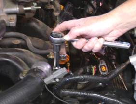
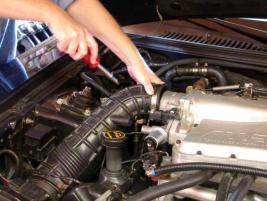
Remove shock tower brace, if equipped.
3.
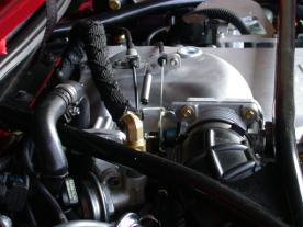
Remove mass air sensor to throttle body tube.
4.
1.
Disconnect negative ground cable from battery.
2.
Remove shock tower brace, if equipped.
3.
Remove mass air sensor to throttle body tube.
4.
 5.
5.  4.
Disconnect vehicle wiring harness connectors
from ignition coils; throttle position sensor, idle air,
4.
Disconnect vehicle wiring harness connectors
from ignition coils; throttle position sensor, idle air,EGR solenoid valve, EGR Pressure Transducer, Temperature Sensors, fuel pressure, and fuel
injector connections. 5. Remove PCV hose from vehicle. 9.
 6.
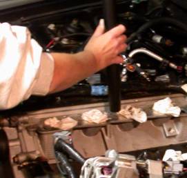
Remove spark plug wires.
7.
Remove idle air valve, hose and silencer
from vehicle.
8.
Remove crankcase vent hose from vehicle.
9.
Disconnect throttle cable (and cruise control
cable if equipped) and mounting bracket from intake
6.
Remove spark plug wires.
7.
Remove idle air valve, hose and silencer
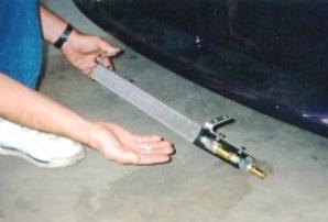
from vehicle.
8.
Remove crankcase vent hose from vehicle.
9.
Disconnect throttle cable (and cruise control
cable if equipped) and mounting bracket from intakemanifold. The cables can now be easily detached from bracket with a pair of pliers. 10. Remove vacuum hoses from vehicle. 11. Drain engine coolant from petcock valve on bottom of radiator. 12.
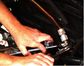
 13.
13.  12.
Relieve fuel system pressure and disconnect spring lock couplings. A special
tool is required for each
12.
Relieve fuel system pressure and disconnect spring lock couplings. A special
tool is required for eachfuel connector. They are available at any auto parts store. 13. Disconnect water heater hose (rear on manifold to firewall) from firewall. 14. Rotate the tensioner with a ratchet and remove the accessory drive belt. 15.
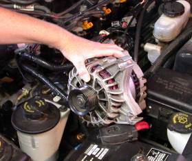 15.
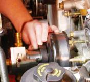
Loosen 2 alternator bolts and remove Alternator.
16.
15.
Loosen 2 alternator bolts and remove Alternator.
16.
 17.
17.  16.
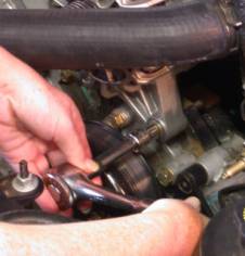
Remove EGR Solenoid.
17.
Loosen EGR tube retaining nut at EGR Valve.
Remove the EGR transducer mounting nuts, and
16.
Remove EGR Solenoid.
17.
Loosen EGR tube retaining nut at EGR Valve.
Remove the EGR transducer mounting nuts, andmove the transducer to the side. Do not remove the hoses. This will allow you to get to the bolt
holding the manifold down. 18.
 20.
20.  18.
Remove Intake Manifold bolts, including the
ones retaining the water outlet.
19.
Remove water outlet and upper radiator hose.
20.
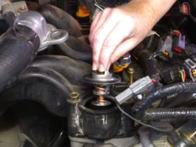
Remove thermostat and O-Ring from the Intake
manifold.
21.
18.
Remove Intake Manifold bolts, including the
ones retaining the water outlet.
19.
Remove water outlet and upper radiator hose.
20.
Remove thermostat and O-Ring from the Intake
manifold.
21.
 23.
23.  21.
Remove Intake Manifold.
22.
Remove Intake Manifold Gaskets.
23.
Vacuum any dirt or debris from the Intake
Manifold flanges.
24.
Cover intake ports with duct tape or equivalent.
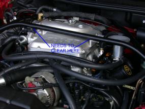
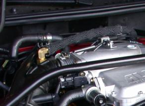
25.
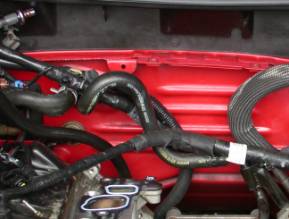
Position the passenger side heater hose out of the way as shown in 26.
26.
21.
Remove Intake Manifold.
22.
Remove Intake Manifold Gaskets.
23.
Vacuum any dirt or debris from the Intake
Manifold flanges.
24.
Cover intake ports with duct tape or equivalent.
25.
Position the passenger side heater hose out of the way as shown in 26.
26.
 27.
27.  26.
Position the drivers side heater hose as
shown to clear new manifold.
27.
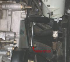
Remove 2 nuts and 1 bolt from power steering
reservoir mount on front cover. Remove lower stud
26.
Position the drivers side heater hose as
shown to clear new manifold.
27.
Remove 2 nuts and 1 bolt from power steering
reservoir mount on front cover. Remove lower studreplace it with the new stud provided, without the integrated nut. 28. Remove front cover bolts, which will need to be replaced for the mounting of the Idler Pulley
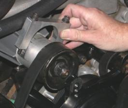
Mount. To determine which bolts need to be removed, if not obvious to you, hold the mount up to
the front cover and position the hole over the stud you just replaced. 29. Position Idler Pulley Mount and retain with bolts provided. (Torque to 17-22 ft-lb.) 28.
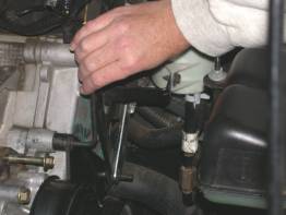 29.
29.  30.
Attach Pulley to Mount and retain with provided
bolts. (Torque to 17-22 ft-lb.) Reinstall power
30.
Attach Pulley to Mount and retain with provided
bolts. (Torque to 17-22 ft-lb.) Reinstall powersteering reservoir bolt and nut. 31.

 31.
Assemble the EGR Valve from the stock manifold
to the new manifold with adapter, bolts and gasket
31.
Assemble the EGR Valve from the stock manifold
to the new manifold with adapter, bolts and gasketprovided. The adapter will allow use of stock Ford shock tower brace. (Torque to 17-22 ft-lb.) 32. Transfer the throttle body from the stock manifold to the new manifold using stock bolts. Reuse the
gasket as long as it is not damaged. 33. Transfer the Idle air control valve from the stock manifold to the new manifold using supplied bolts.
Reuse the gasket as long as it is not damaged. 34. Transfer the engine temperature sensor from the driver side of the old manifold, to the underside of
the water crossover of the new manifold. Transfer the engine temperature sensor from the passenger
side of the old manifold, to the topside of the water crossover on the new manifold. (Use Teflon
sealant) 35-36.
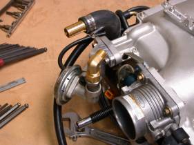
 35a
35a 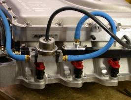 35.
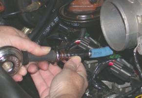
Transfer the fuel pressure regulator from the stock fuel rail to the
fuel rail block as shown. Install
35.
Transfer the fuel pressure regulator from the stock fuel rail to the
fuel rail block as shown. Installthe short fuel hose between the “IN” side of the fuel block and the fuel rail adapter as shown. Install
the SFPR over the regulator and install the V-band clamp. Photo 35a. shows installation for the
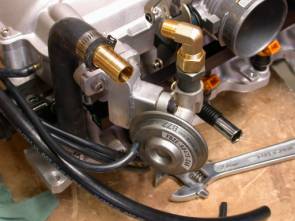
optional 9 p.s.i. system. 36. Mount the SFPR using the supplied spacers as shown. (not used on 9 p.s.i. system.) 37. Transfer one stock fuel rail bolt from the old manifold to the rear of the new manifold (driver side).
This will allow stock ground wire to be used. Be sure to retain the phenolic spacer supplied to
insulate the fuel rails from the manifold. (see 71) 38. Transfer the plastic EGR solenoid to new manifold using the bolts supplied, and attach the hose from
the manifold to the lower port. Connect the upper port to the EGR valve with supplied hose. 39. Transfer fuel pressure test (schraeder) valve from old fuel rail to new fuel rail (driver side). Use
Teflon tape. 40a.
 40b.
40b. 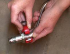
40c.
 40.
Since the EGR Valve has been re-located,
the EGR Tube must be “Modified”. This can be done
40.
Since the EGR Valve has been re-located,
the EGR Tube must be “Modified”. This can be donewith common hand tools. (shown Sears 51252 tubing cutter) The tube must be cut in two (2) places
and mended with brass crush collars on the end of a flexible stainless steel tube. Cut the tube as
shown. The small end cut off in 40b needs to be assembled as shown in 40c. 41a.
 41b.
41b.  41.
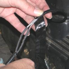
Tighten all EGR feed tube connections. The photo is shown without
the woven heat shield for
41.
Tighten all EGR feed tube connections. The photo is shown without
the woven heat shield forclarity. Be sure to install heat shield supplied before continuing. Position the EGR tube as shown prior
to installing the manifold. 42.
 43.
43. 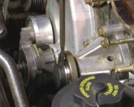 44.
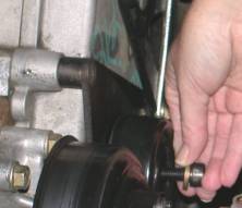
44.  42.
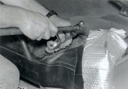
Loosen 4 bolts retaining water pump pulley,
and remove pulley.
43.
Remove black plastic protective sleeve on
water pump shaft. This may require a hammer and sharp
42.
Loosen 4 bolts retaining water pump pulley,
and remove pulley.
43.
Remove black plastic protective sleeve on
water pump shaft. This may require a hammer and sharpchisel or a sharp knife. Try not to mar the precision machined surface under the sleeve. 44. Attach the intercooler water pump with the 4 supplied bolts. These can be tightened with a standard
8mm box end wrench. A pair of water pump pliers (spanning 2 of the bolts) can be used to keep the
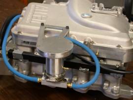
assembly still while tightening each bolt. 45. Re-install the intake manifold gaskets on to the cylinder heads. It is better to use new gaskets for use
with P.I. heads. Maker sure they have not been damaged in any way. Position wiring harness and
EGR tube as shown. Be sure EGR transducer hoses are attached and nuts are installed as these are
difficult to reach once the manifold is installed. Protective tape or equivalent must be removed from
the ports now.
45. 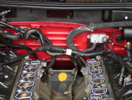 46.
46. 
during this procedure. The wiring harness will need to be lifted slightly at the rear of the engine to
allow it back into the proper position. The wiring harness should be just above the mounting flange of
the manifold. This is best performed with a person on each side of the vehicle to gently guide it into
place. 47.
 48.
48.
 47.
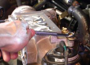
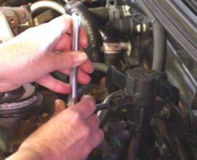
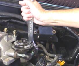
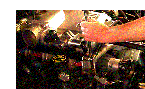
Install the intake manifold bolts supplied
(9 hex flange, and 1 long cap screw) and tighten in a
47.
Install the intake manifold bolts supplied
(9 hex flange, and 1 long cap screw) and tighten in acrisscross pattern. Repeat this procedure until all bolts are snug and then torque to 17-22 ft-lbs. 48. Connect feeder tube fitting to EGR Valve and tighten. There may be some slight alignment of the
flexible stainless steel tube required before this is achievable. Be sure the EGR tube is as far as
possible from the wiring . 49. Re-install spark plug wires. Route the wires along the front under the nose of the blower in the
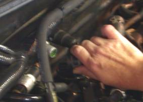
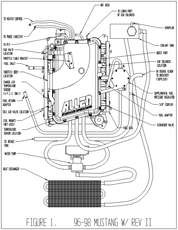
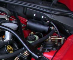
engine valley. 50. Attach the Evaporative canister hose to the passenger side 3/8” vacuum tube. (See Figure 1) The
existing hose may need to be shortened slightly for a proper fit. 51. Using supplied hose, connect the hose from PCV valve to the driver side 3/8” vacuum tube. (See Figure 1)
 53.
53.
 52.
Connect vacuum hoses to heater and purge
canister. These hoses have brass reducers attached to
52.
Connect vacuum hoses to heater and purge
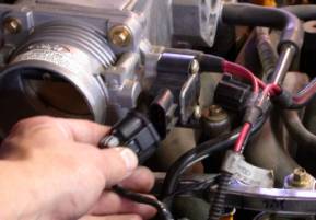
canister. These hoses have brass reducers attached tothem to accommodate the mating hose size. (See Figure 1) 53. The wires for the passenger side coolant temp sensor (6”), drivers side coolant temp sensor (16”),
idle air valve (10”), alternator (18”) and throttle body (10”) need to be lengthened. Supplied in the
kit are color-coded wires and crimp connectors as well as black corrugated split loom. We recommend
soldering and shrink-tubing the connections if possible. 54. Re-attach the throttle and cruise control cables and return spring. 55.
 56.
56.  55.
Snap the fuel line connector into the rear of the driver side fuel rail.
The fuel return line needs to be
55.
Snap the fuel line connector into the rear of the driver side fuel rail.
The fuel return line needs to berouted from the drivers side to the passenger side and connected with the supplied snap fitting. The
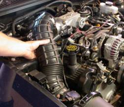
supplied connector is a push-on fitting. DO NOT us a hose clamp on any of the blue fuel lines. 56. Install the rubber air inlet tube from the mass air flow sensor to throttle body and tighten clamps 57. Re-attach formed rubber hose from air inlet to idle air valve. This may require some trimming! 58. Connect valve cover breather hose from driver side valve cover to air inlet tube with 5/8” hose and
90° elbow. 59. Mark hole locations for the intercooler reservoir in windshield wiper motor cover. Check for proper
location using the tank, and drill holes (1/4” drill). The small dent in the bottom of the tank should
just clear the brake cylinder. 60. Attach Intercooler coolant tank to firewall cover with supplied screws. 59.
 61.
61. 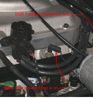 61.
Attach ground wire to the fuel rail bolt as shown.
62.
61.
Attach ground wire to the fuel rail bolt as shown.
62.
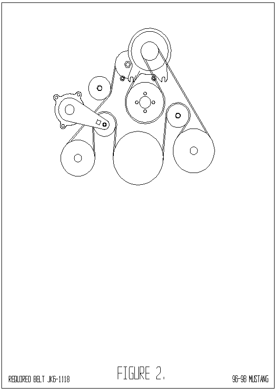
 62.
Route the supplied drive belt appropriately and position the alternator
bracket. Retain with 2 bolts and
62.
Route the supplied drive belt appropriately and position the alternator
bracket. Retain with 2 bolts andloosely tighten. (Study Figure 2 thoroughly before attempting this step.) 63. Install the Drive Housing Clamp and tighten bolts to 7-10 ft lbs. 64. Now the alternator bracket can be tightened to 17-22 ft-lbs. 65. Thread bolts (and washers) into the alternator bracket top left and lower right as viewed from front
of car. 66. Position alternator into bracket while placing the belt over the proper pulleys. The tensioner must be
relieved to its slack position during this process. I may be easier to slip the water pump pulley on last
as it has no flange. Once the belt is correctly positioned over all pulleys, tighten the supplied bolts to
17-22 ft-lbs.
 67.
67.
 67.
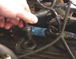
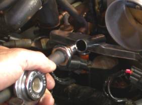
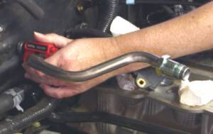
Re-install thermostat and o-ring. Be sure to use the supplied spacers.
68.
Cut the stock upper radiator hose, and reassemble using 45 degree elbow,
and hose clamps supplied.
67.
Re-install thermostat and o-ring. Be sure to use the supplied spacers.
68.
Cut the stock upper radiator hose, and reassemble using 45 degree elbow,
and hose clamps supplied.Be sure to rotate thermostat housing away from alternator pulley as far as possible to insure proper
working clearances. 68a.
 68b.
68b. 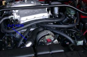 69.
69.
 69.
With the Heat Exchanger for the Intercooler bolted to its mounting brackets,
position the assembly
69.
With the Heat Exchanger for the Intercooler bolted to its mounting brackets,
position the assemblyunder the valence toward the passenger side of the opening and the fittings on the driver side. Mark
hole positions using a magic marker. Remove assembly and drill holes using #29 cobalt drill bit
(supplied) for the self tapping screws (supplied). Remove the mounting brackets from the Heat
Exchanger. Now you can attach the mounting brackets to the cross-member using access through the
hole in the bracket. The Heat Exchanger can now be bolted to the brackets. 70. Connect the hoses to heat exchanger, water pump, intercooler, and tank as shown in Figure 1. 71.
 73.
73.  71.
For cars with stock Ford shock tower braces, install the shock tower brace
and snug down the bolts.
71.
For cars with stock Ford shock tower braces, install the shock tower brace
and snug down the bolts.The brace will most likely be close to the throttle position sensor and the forward bolt of the SFPR
mount. Mark these locations with tape, remove the brace, and form a small dent in the underside of
the brace in each location. This can be done easily if you have access to a hydraulic press. If not,
put duct tape over the location to keep the paint from chipping and tap in the dent with a small
hammer. The metal is not very thick and deforms easily. The air inlet hose should also be marked
with a magic marker around the brace. Trim the reinforcing ribs from the rubber tube where they hit
the brace. 72. Reinstall the brace and tighten all bolts. 73. Re-connect heater hose, looping the hose over the top of the shock tower brace. 74. Re-fill engine cooling system and re-install cap. Close the petcock first! 75. Fill the Intercooler water tank with coolant (50/50 Water Glycol mixture). It may be necessary to
burp the system by loosening the petcock on the top of the water pump. Install the Radiator Cap. 76. Your kit is equipped with a high flow fuel pump, it can be installed now. Follow instructions included
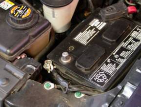
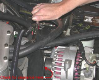
with the pump, and in the supplement to this manual. 77. The battery cable can now be connected. Check for any stray tools or spare parts, which may hinder the starting of the vehicle. Start engine and check for any fuel or coolant leaks, as well as adequate working clearance between
parts. Remove intercooler tank cap, and verify flow, top off if necessary. (If you do not see water
flowing inside the intercooler reservoir the pump is not properly primed.) Replace cap. You’re done!
FUEL PUMP INSTALL
1.
Remove the gas tank from car. On the Mustang this can be done by removing
the metal screw that holds
the support bracket for the gas filler tube,
and the 4 strap bolts. Unplug the electrical connection at the
rear of
the gas tank and the tank will then pull out of the filler tube and drop
down. You can then
release the plastic clips that hold the fuel lines
together.
the metal hangers out of their rubber mounts. (Spray WD 40 on the rubber mounts and the metal
hangers will pull out). Remove the gas filler hose clamp at the gas tank and also the vent hose clamp by
the filler tube and the vent hose clamp over the differential. Remove the 4 strap bolts and drop down
the gas tank.You can now release the plastic clips that hold the fuel lines together and pull off the
electrical connection.
2. Remove the large nut, that holds the fuel pump/fuel level assembly.
3. Remove the fuel pump/fuel level assembly.
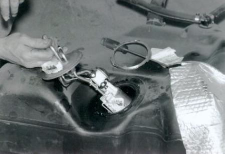
4. Pry the fuel filter off the fuel pump noting which way the large part of the filter is pointing.
5. Pull the production fuel pump up and slide it
out of its mount. Cut the electrical wires and remove the
fuel pump.
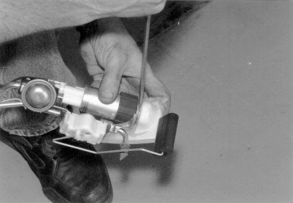
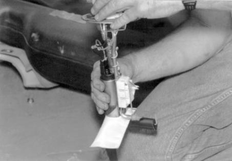
6. Slide the bottom rubber over the new fuel pump.

7. Slide the rubber hose and hose clamps over
the fuel pump outlet. Slide the fuel pump into its mount and
tighten the
hose clamps. On the Thunderbird this hose will need to be shortened and
the bend
straightened out.
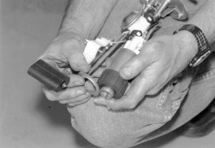
8. Hook up the electrical wires using the
crimp connectors supplied with the fuel pump. 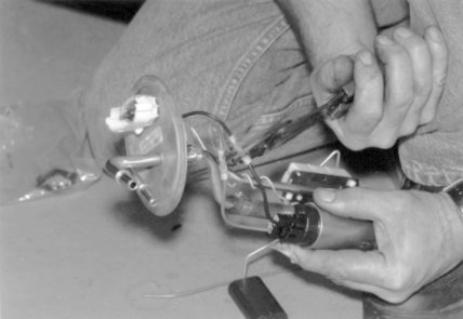
9. Push the fuel filter securely on the fuel pump. Make sure it is positioned in the proper direction.
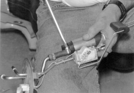
10. Slide the fuel pump into the fuel tank and make
sure the O ring seal is in the O ring groove. Tighten the
large nut that
holds the fuel pump in the tank and Install the fuel tank on the car.
The plastic safety
clips that lock the fuel lines to the fuel tank are
inexpensive and at your Ford dealer if needed. 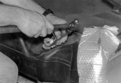
Thank you for your recent purchase of the Allen Engine Development Inc.
REV II supercharger kit for your 19__ Mustang GT
Your Kit serial #________
Calibration Code___________
Kit Model 6 psi ____ 9 psi _____
Date purchased_______
Warranty period______
supercharger systems.)