INSTALLATION INSTRUCTIONS
2000-2003 Mustang GT Supercharger
Kit
Congratulations on choosing what we feel is the best supercharger kit on the market. Proper installation is the key to long and trouble free operation. Please read and understand thoroughly all of the instructions presented here. We have made major improvements on the Rev II Kit, especially on issues associated with installation time. Every possible effort has been made to assure a quality and complete product. Please check the completeness and condition of your kit as received. If there are any missing or damaged parts, please call us. We will make every effort to remedy the situation in a timely manner. Please note that the water tank in some kits has a dent in the bottom, not to worry. This is supposed to be there to clear the brake system accumulator.
1.
 4.
4.
1. Disconnect negative ground cable from battery.
2. Remove passenger side door sill and kick panel. The sill just snaps out, while the kick panel has some push pins holding it in place.
3. Remove the EEC processor. A few electrical connectors and mounting brackets must be removed and unplugged to accomplish this. Put in a safe place for later service.
4. Remove mass air sensor to throttle body tube.
5.
 6.
6.
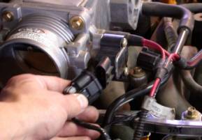
5. Disconnect vehicle wiring harness connectors from ignition coils; throttle position sensor, idle air, EGR solenoid valve, EGR Pressure Transducer, Temperature Sensors, fuel pressure, and fuel injector connections.
6. Remove PCV hose from vehicle.
7.
 10.
10.
7. Remove ignition coils.
8. Remove idle air valve, hose and silencer from vehicle.
9. Remove crankcase vent hose from vehicle.
10. Disconnect throttle cable (and cruise control cable if equipped) and mounting bracket from intake manifold. The cables can now be easily detached from bracket with a pair of pliers.
11. Remove vacuum hoses from vehicle.
12. Drain engine coolant from petcock valve on bottom of radiator.
13.
 14.
14.
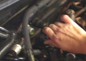
13. Relieve fuel system pressure and disconnect spring lock couplings. A special tool is required for this.
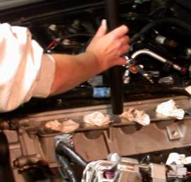
14. Disconnect water heater hose (rear on manifold to firewall) from firewall. (snap connector)
15. Remove accessory drive belt.
16.
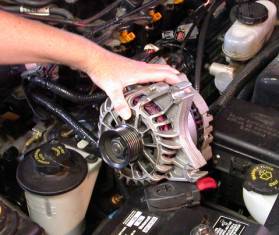
16. Loosen 2 alternator bolts and remove Alternator. (Set aside)
17.
 18.
18.
17. Remove EGR Solenoid and Transducer from mount.
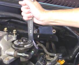
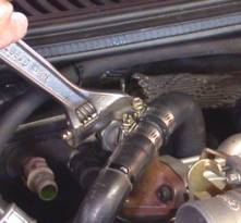
18. Loosen EGR tube retaining nut at EGR Valve.
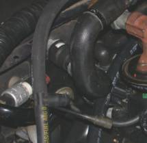
19.
 21.
21.
19. Remove Intake Manifold bolts, including the ones retaining the water outlet.
20. Remove water outlet and upper radiator hose.
21. Remove thermostat and O-Ring from the Intake manifold.
22.
 24.
24.
22. Remove Intake Manifold.
23. Remove Intake Manifold Gaskets.
24. Vacuum any dirt or debris from the Intake Manifold flanges and cover with duct tape or equivalent.
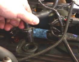
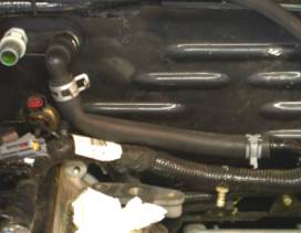
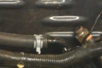
25. Remove the formed rubber hose (5/8”) from the firewall and water pump inlet tube.
26. Detach the snap connector (2001 and newer vehicles) from the hose (5/8”) and install onto the short end of the supplied L shaped hose. If 2000 or older vehicle retain stock hose.
27.
 28.
28.

27. Install the L shaped hose onto the vehicle using the spring hose clamps. (again only for 2001 and newer)
28-30.
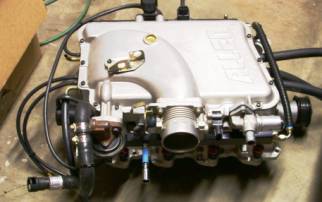
28. Transfer the EGR Valve from the stock manifold to the new manifold with bolts and gasket provided. (Torque to 17-22 ft-lb.) Be sure to replace the gasket to assure proper functioning.
29. Transfer the throttle body from the stock manifold to the new manifold using stock bolts. Reuse the gasket as long as it is not damaged.
30. Transfer the Idle air control valve from the stock manifold to the new manifold using supplied bolts. Reuse the gasket as long as it is not damaged.
31. Transfer the engine temperature sensor from the old manifold, to the new one. (Use Teflon sealant)
32. Remove heater hose from stock intake manifold and attach it to the new manifold using the supplied clamp.
30-36.
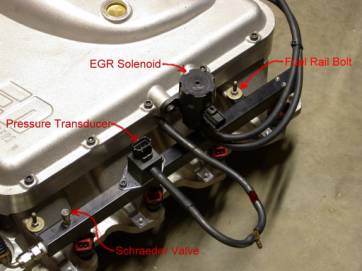
33. Transfer one fuel rail bolt from the old manifold to the rear of the new manifold (driver side). Be sure to retain the phenolic spacer supplied to insulate the fuel rails from the manifold.
34. Transfer EGR solenoid to new manifold using the bolts supplied, and attach the hose from the manifold to the lower port. Connect the upper port to the EGR valve with supplied hose.
35. Transfer fuel pressure test (schraeder) valve from old fuel rail to new fuel rail (driver side). Use Teflon tape.
36. Transfer the fuel pressure transducer to the new fuel rail and retain with the supplied bolts. Connect the hose to the plenum.
37.
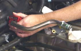
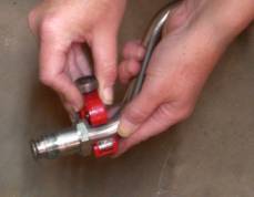
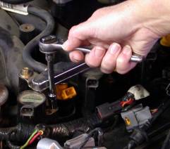
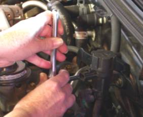
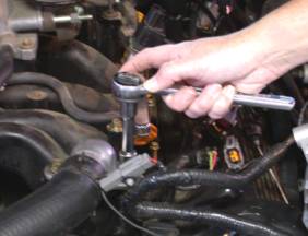
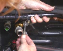
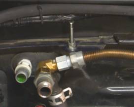
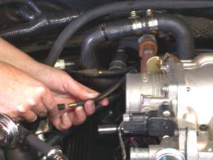
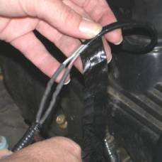
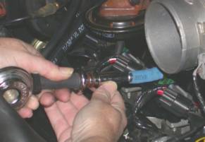
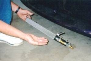
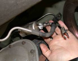
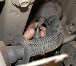
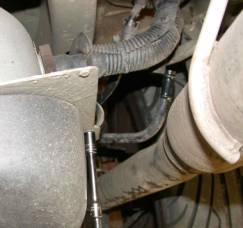
37. Since the EGR Valve has been re-located, the EGR Tube must be “Modified”. This can be done with common hand tools. (shown Sears 51252 tubing cutter) The tube must be cut in two (2) places and mended with brass crush collars on the end of a flexible stainless steel tube.
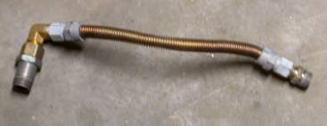
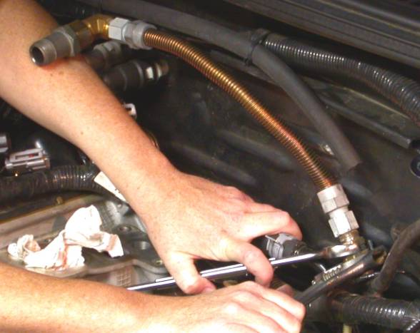
38. Tighten all EGR feed tube connections. The photos are shown without the woven heat shield for clarity. (Be sure to install hear shield before continuing)
39.
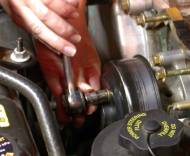
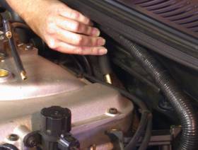
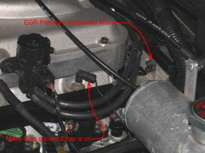
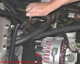
39. The new location of the EGR valve requires a stand-off for the wiring loom running across the firewall. Snap the harness out of the firewall mount (passenger side) and place standoff (supplied) in between. Reinsert harness into standoff.
40
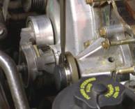
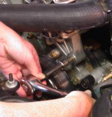
40. Loosen 4 bolts retaining water pump pulley, and remove pulley.
41. Remove black plastic protective sleeve on water pump shaft. This may require a hammer and sharp chisel or a sharp knife. Try not to mar the precision machined surface under the sleeve.
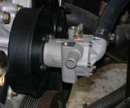
42. Attach the intercooler water pump with the 4 supplied bolts. These can be tightened with a standard 8mm box end wrench. A pair of water pump pliers (spanning 2 of the bolts) can be used to keep the assembly still while tightening each bolt.
43. Re-install the intake manifold gaskets on to the cylinder heads. Maker sure they have not been damaged in any way. (Protective tape or equivalent must be removed now)
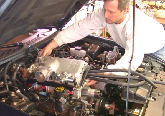
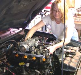
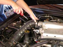
44. Set the Intake manifold / Supercharger assembly onto the engine. Be sure not to damage the gaskets during this procedure. The wiring harness will need to be lifted slightly at the rear of the engine to allow it back into the proper position. This is best performed with a person on each side of the vehicle to gently guide it into place.
45.
 46.
46.
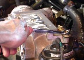
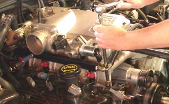
45. Install the intake manifold bolts supplied (9 hex flange, and 1 long cap screw) and tighten in a crisscross pattern. Repeat this procedure until all bolts are snug and then torque to 17-22 ft-lbs.
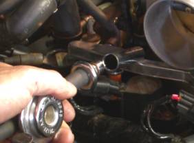
46. Connect feeder tube fitting to EGR Valve and tighten. There may be some slight alignment of the flexible stainless steel tube required before this is achievable.
47. Re-install ignition coils and retaining bolts, and tighten.
48. Plug in electrical connectors for the ignition coils, fuel injectors, throttle body, idle air control valve, etc.
49. Re-connect heater hose to firewall connector.
50.
 51.
51.
50. Attach the Evaporative canister hose to the passenger side 3/8” vacuum tube. (See Figure 1) The existing hose may need to be shortened slightly for a proper fit.
51.
Using supplied hose, connect the hose from PCV valve to the driver side 3/8”
vacuum tube. (See Figure 1)
52.
 53A.
53A.
52. Connect vacuum hoses to heater and purge canister. These hoses have brass reducers attached to them to accommodate the mating hose size. (See Figure 1)
53B.
 53C.
53C.
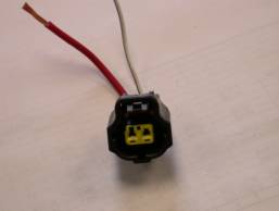
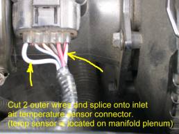
53. The wires for the inlet air temperature sensor need to be lengthened. Supplied in the kit are color-coded wires and crimp connectors as well as black corrugated split loom. We recommend soldering and shrink-tubing the connections if possible. Connect the wire to the new temperature sensor located in the plenum. NOTE: On 2002-2003 vehicles the temperature sensor is integral with the mass air meter. This requires a new plug (supplied see 53C) and the outer 2 wires need to be cut and spliced from the MAF meter. Note: some kits may have the wires attached to ACT sensor prior to shipment, and no connector!
54. Re-attach the throttle and cruise control cables and return spring.
55.
 56.
56.
55. Snap the fuel line connector into the rear of the driver side fuel rail.
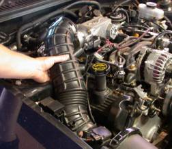
56. Install the rubber air inlet tube from the mass air flow sensor to throttle body and tighten clamps
57. Re-attach formed rubber hose from air inlet to idle air valve. This may require some trimming!
58. Connect valve cover breather hose from driver side valve cover to air inlet tube with 5/8” hose and 90° elbow.
59. Mark hole locations in windshield wiper motor cover using pattern supplied on Figure 2. Check for proper location using tank, and drill holes (1/4” drill).
60. Attach Intercooler coolant tank to firewall cover with supplied hardware.
61.
61. Attach EGR pressure transducer to supplied bracket. Then attach bracket to fuel rail. Make sure the hoses and electrical connector are not twisted or disconnected.
63.
 69
69
62. Route the supplied drive belt appropriately and position the alternator bracket. Retain with 2 bolts and loosely tighten. (Study Figure 2 thoroughly before attempting this step.)
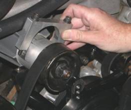
63. Install the Drive Housing Clamp and tighten bolts to 7-10 ft lbs.
64. Now the alternator bracket can be tightened to 17-22 ft-lbs.
65. Thread bolts (and washers) into the alternator bracket.
66. Position alternator into bracket while placing the belt over the proper pulleys. The tensioner must be relieved to its slack position during this process. Once the belt is correctly positioned over all pulleys, tighten the supplied bolts to 17-22 ft-lbs.
67. Connect electrical connectors to alternator if previously removed.
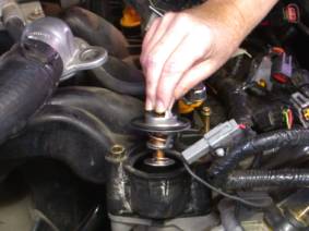
68. Install supplied 180° thermostat and o-ring.
69. Replace the upper radiator hose with supplied hose assembly. Be sure to rotate thermostat housing away from alternator pulley to insure proper working clearances (99-01 only).
70.
70. With the Heat Exchanger for the Intercooler bolted to its mounting brackets, position the assembly under the valence toward the passenger side of the opening and the fittings on the driver side. Mark hole positions using a magic marker. Remove assembly and drill holes using #29 drill bit (supplied) for the self tapping screws (supplied). Remove the mounting brackets from the Heat Exchanger. Now you can attach the mounting brackets to the cross-member using access through the hole in the bracket. The Heat Exchanger can now be bolted to the brackets.
71. Connect the hoses to heat exchanger, water pump, intercooler, and tank as shown in Figure 1.
72. Re-fill engine cooling system and re-install cap. Close the petcock first!
73. Fill the Intercooler water tank with coolant (50/50 Water Glycol mixture). It may be necessary to burp the system by loosening the petcock on the top of the water pump. Install the Radiator Cap.
74. Your kit is equipped with a high flow fuel pump. On a suitable rack or supported by jack stands, remove the filter connector from the filter.
74.
 75a.
75a.
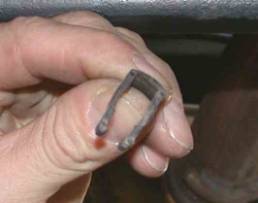
75. Disconnect the fuel vapor lines from the fuel filler neck. Remove the little plastic clip before attempting this!
75b.
 76.
76.
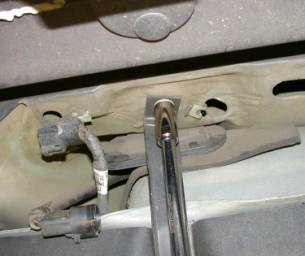
76. Remove screw from the filler tube support bracket.
77.
77. Unplug the electrical connector from the fuel pump/sender unit. Unclip the connector from the underside of the body. Remove the bolts from the fuel tank support straps. There are two of these. Be sure to support the tank before completely removing these. Gently massage the tank out disconnecting appendages as they appear.
78.
 79.
79.
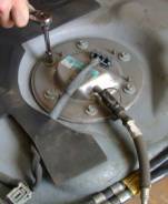
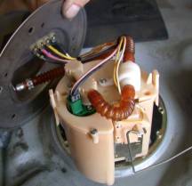
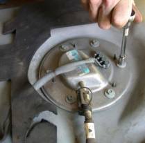
78. The fuel pump assembly can be accessed through the cover.
79. Remove the 6 bolts, and disconnect the connector on the fuel pump.
80.
 81.
81.
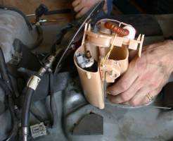
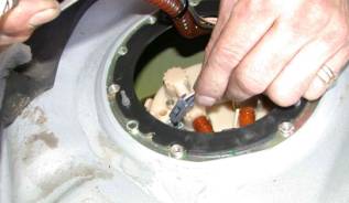
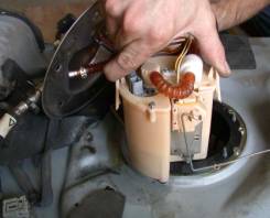
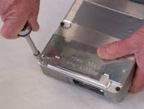
80. The pump can be lifted out of the tank now. Remove the screws from the top of the “can”. The top of the “can” can now be removed by sqeezing the catches and pulling up. The stock pump can now be removed and replaced with the high flow unit. The new pump is supplied with 2 new filter bags. Replace them if necessary.
81. Re-assemble the “can” an put it back into the tank.
81.
 82.
82.
82. Re-install the fuel tank and be sure to re-connect all the hoes, and connectors that were removed during disassembly.
83.
 84.
84.
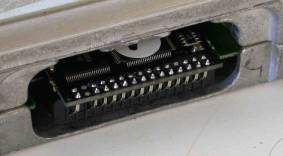
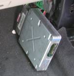
83. Locate the EEC processor, and remove the cover bolts and cover.
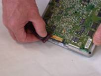
84. Gently scrape away rubber coating from connector area using your fingernail, (Popsicle stick, or plastic fork broken in half work too).
85.
 86.
86.
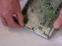
85. Gently clean terminals with scotch brite pad provided, until a slight copper color is detected. Clean with rubbing alcohol (or similar).
86. Plug in chip as shown.
87. Plug the EEC processor and other electrical connectors back into the vehicle harness. Leave the EEC laying on the floor until proper operation is verified. (shown in photo without chip)
87.
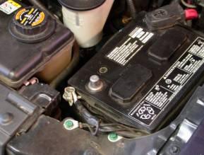
88. The battery cable can now be connected.
89. Check for any stray tools or spare parts, which may hinder the starting of the vehicle.
90. Start engine and check for any fuel or coolant leaks, as well as adequate working clearance between parts. Remove intercooler tank cap, and verify flow, top off if necessary. Replace cap.
91. The chip operation being verified now, put some duct tape or equivalent over the opening in the EEC. The EEC processor can now be re-inserted into its mounting location.. The kick panel and door sill can also be replaced.
92. You’re done!
Dear
Customer:
Thank
you for your recent purchase of the Allen Engine Development Inc. supercharger
kit for your 200_ Mustang GT
Your
Kit serial #________
Calibration
Code___________
Kit
Model 6 psi ____ 9 psi _____
Date
purchased_______
Warranty
period______
Please keep this in your records in the event of a
warranty claim.
(Warning: We highly
recommend forged pistons and rods for use with all 9 p.s.i. supercharger systems.)